Products: Abaqus/CFD Abaqus/CAE
Benefits: You can now change the coordinate system in which you specify a fluid velocity boundary condition in Abaqus/CAE. This enhancement provides a finer level of control when defining these types of boundary conditions.
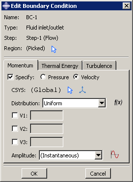
Description: By default, the global coordinate system is used when defining any boundary condition. For a fluid inlet and outlet velocity boundary condition and a fluid wall velocity boundary condition, you can now select another coordinate system in which to specify the boundary condition; only a rectangular coordinate system can be selected. To avoid precision loss due to finite precision arithmetic, values for all three components must be specified when applying fluid velocity boundary conditions in a coordinate system other than the global coordinate system. Abaqus/CAE transforms these values and applies them in the global coordinate system. The CSYS option available in the Edit Boundary Condition dialog box (shown in Figure 8–3) allows you to do the following:
Select an existing datum coordinate system in the viewport.
Select an existing datum coordinate system by name.
Create a new datum coordinate system.
Load module:
    Create Boundary Condition; Category: Fluid, Types: Fluid inlet/outlet or Fluid wall condition;
    specify velocity boundary conditions, CSYS: select rectangular coordinate system,
    enter V1, V2, and V3