Product: Abaqus/CAE
Benefits: You can now add a boundary layer composed of one or more layers of wedge elements extruded from the exterior faces surrounding a tetrahedral mesh. Adding layers of small elements along the walls allows improved analysis of boundary effects in fluid flow and heat transfer analyses.
Description: In previous releases of Abaqus, the construction of a boundary layer near external surfaces would have been a tedious process. Now you can easily specify a boundary layer when you select the mesh controls for a region. The thinnest layers of wedge elements are at the walls, where boundary effects are greatest; and you can increase the layer thickness toward the interior of the model.
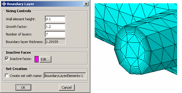
When you assign mesh controls to regions and choose a tetrahedral element shape, the option to insert a boundary layer appears near the bottom of the Mesh Controls dialog box. Click the Assign Controls button to access the Boundary Layer dialog box so that you can define the layers of wedge elements. You must enter the following information:
The height (thickness) of the element layer adjacent to the walls.
A growth factor that determines the increase in height of each successive layer inward from the walls.
The number of wedge element layers.
Mesh module:
    MeshControls: Element shape: Tet: toggle on Insert boundary layer, and click Assign Controls