Product: Abaqus/CAE
Benefits: You can now display multiple view cut “slices” that show the state of your model at a series of locations. Slices can be displayed at regularly spaced intervals along the range of the active view cut or at locations along a predefined path in your session. This enhancement provides a helpful visualization tool for investigation of several locations in your model at once, especially for curved parts.
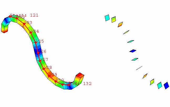
Description: Abaqus 6.11 introduced an enhancement that enables you to display a series of free bodies at regular intervals along the range of the active view cut. This release expands upon that capability by allowing you to display a series of view cut slices for a series of locations in your model. You can display slices at regular intervals along the range of the active view cut, or you can position the slices so that they follow a predefined path in your session. The left side of Figure 14–2 shows a simple extruded part with a node-based path defined along one of its curved edges; the right side shows the view cut slices positioned at the nodes of that path.
You can also display a free body cut at each view cut slice location to show resultant forces and moments. When you use slicing to display multiple free body cuts, Abaqus/CAE aligns one of the tangential components of each free body cut along the same Y-axis. You can specify this Y-axis value in the Free Body tabbed page of the View Cut Options dialog box.You can also use slicing to control the data that are included when you investigate the X–Y data along a path. By default, the XY Data from Path functionality returns data from the points or nodes that comprise the path. However, you can specify instead that Abaqus/CAE obtain data at a regular series of intervals along the path.
Visualization module:
    View cut options: Slicing tabbed page: Display slicing
    View cut options: Free Body tabbed page: Y-axis setting for Normal and tangential component resolution
    XY Data from Path dialog box: Uniform spacing