Products: Abaqus/Standard Abaqus/CAE
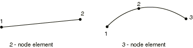
This section provides a reference to the axisymmetric membrane elements available in Abaqus/Standard.
Coordinate 1 is r, coordinate 2 is z. At ![]() , the r-direction corresponds to the global X-direction and the z-direction corresponds to the global Y-direction. This is important when data are required in global directions. Coordinate 1 should be greater than or equal to zero.
, the r-direction corresponds to the global X-direction and the z-direction corresponds to the global Y-direction. This is important when data are required in global directions. Coordinate 1 should be greater than or equal to zero.
Degree of freedom 1 is ![]() , degree of freedom 2 is
, degree of freedom 2 is ![]() . Generalized axisymmetric elements with twist have an additional degree of freedom, 5, corresponding to the twist angle
. Generalized axisymmetric elements with twist have an additional degree of freedom, 5, corresponding to the twist angle ![]() (in radians).
(in radians).
Abaqus/Standard does not automatically apply any boundary conditions to nodes located along the symmetry axis. You must apply radial or symmetry boundary conditions on these nodes if desired.
Point loads and moments should be given as the value integrated around the circumference; that is, the total value on the ring.
| Input File Usage: | *MEMBRANE SECTION |
In addition, use the following option for variable thickness membranes: *NODAL THICKNESS |
| Abaqus/CAE Usage: | Property module: Create Section: select Shell as the section Category and Membrane as the section Type |
You cannot define variable thickness membranes in Abaqus/CAE. |
Distributed loads are specified as described in “Distributed loads,” Section 33.4.3.
Load ID (*DLOAD): BR
Abaqus/CAE Load/Interaction: Body force
Units: FL3
Description: Body force in the radial (1 or r) direction.
Load ID (*DLOAD): BZ
Abaqus/CAE Load/Interaction: Body force
Units: FL3
Description: Body force in the axial (2 or z) direction.
Load ID (*DLOAD): BRNU
Abaqus/CAE Load/Interaction: Body force
Units: FL3
Description: Nonuniform body force in the radial direction with magnitude supplied via user subroutine DLOAD.
Load ID (*DLOAD): BZNU
Abaqus/CAE Load/Interaction: Body force
Units: FL3
Description: Nonuniform body force in the axial direction with magnitude supplied via user subroutine DLOAD.
Load ID (*DLOAD): CENT
Abaqus/CAE Load/Interaction: Not supported
Units: FL4 (ML3T2)
Description: Centrifugal load (magnitude is input as ![]() , where
, where ![]() is the mass density per unit volume,
is the mass density per unit volume, ![]() is the angular velocity). Since only axisymmetric deformation is allowed, the spin axis must be the z-axis.
is the angular velocity). Since only axisymmetric deformation is allowed, the spin axis must be the z-axis.
Load ID (*DLOAD): CENTRIF
Abaqus/CAE Load/Interaction: Rotational body force
Units: T2
Description: Centrifugal load (magnitude is input as ![]() , where
, where ![]() is the angular velocity). Since only axisymmetric deformation is allowed, the spin axis must be the z-axis.
is the angular velocity). Since only axisymmetric deformation is allowed, the spin axis must be the z-axis.
Load ID (*DLOAD): GRAV
Abaqus/CAE Load/Interaction: Gravity
Units: LT2
Description: Gravity loading in a specified direction (magnitude input as acceleration).
Load ID (*DLOAD): HP
Abaqus/CAE Load/Interaction: Not supported
Units: FL2
Description: Hydrostatic pressure applied to the element reference surface and linear in global Z. The pressure is positive in the direction of the positive element normal.
Load ID (*DLOAD): P
Abaqus/CAE Load/Interaction: Pressure
Units: FL2
Description: Pressure applied to the element reference surface. The pressure is positive in the direction of the positive element normal.
Load ID (*DLOAD): PNU
Abaqus/CAE Load/Interaction: Not supported
Units: FL2
Description: Nonuniform pressure applied to the element reference surface with magnitude supplied via user subroutine DLOAD. The pressure is positive in the direction of the positive element normal.
Load ID (*DLOAD): TRSHR
Abaqus/CAE Load/Interaction: Surface traction
Units: FL2
Description: Shear traction on the element reference surface.
Load ID (*DLOAD): TRSHRNU(S)
Abaqus/CAE Load/Interaction: Not supported
Units: FL2
Description: Nonuniform shear traction on the element reference surface with magnitude and direction supplied via user subroutine UTRACLOAD.
Load ID (*DLOAD): TRVEC
Abaqus/CAE Load/Interaction: Surface traction
Units: FL2
Description: General traction on the element reference surface.
Load ID (*DLOAD): TRVECNU(S)
Abaqus/CAE Load/Interaction: Not supported
Units: FL2
Description: Nonuniform general traction on the element reference surface with magnitude and direction supplied via user subroutine UTRACLOAD.
Foundations are specified as described in “Element foundations,” Section 2.2.2.
Load ID (*FOUNDATION): F
Abaqus/CAE Load/Interaction: Elastic foundation
Units: FL3
Description: Elastic foundation. For MGAX elements the elastic foundations are applied to degrees of freedom ![]() and
and ![]() only.
only.
Surface-based distributed loads are specified as described in “Distributed loads,” Section 33.4.3.
Load ID (*DSLOAD): HP
Abaqus/CAE Load/Interaction: Pressure
Units: FL2
Description: Hydrostatic pressure on the element reference surface and linear in global Z. The pressure is positive in the direction opposite to the surface normal.
Load ID (*DSLOAD): P
Abaqus/CAE Load/Interaction: Pressure
Units: FL2
Description: Pressure on the element reference surface. The pressure is positive in the direction opposite to the surface normal.
Load ID (*DSLOAD): PNU
Abaqus/CAE Load/Interaction: Pressure
Units: FL2
Description: Nonuniform pressure on the element reference surface with magnitude supplied via user subroutine DLOAD. The pressure is positive in the direction opposite of the surface normal.
Load ID (*DSLOAD): TRSHR
Abaqus/CAE Load/Interaction: Surface traction
Units: FL2
Description: Shear traction on the element reference surface.
Load ID (*DSLOAD): TRSHRNU(S)
Abaqus/CAE Load/Interaction: Surface traction
Units: FL2
Description: Nonuniform shear traction on the element reference surface with magnitude and direction supplied via user subroutine UTRACLOAD.
Load ID (*DSLOAD): TRVEC
Abaqus/CAE Load/Interaction: Surface traction
Units: FL2
Description: General traction on the element reference surface.
Load ID (*DSLOAD): TRVECNU(S)
Abaqus/CAE Load/Interaction: Surface traction
Units: FL2
Description: Nonuniform general traction on the element reference surface with magnitude and direction supplied via user subroutine UTRACLOAD.
Surface-based incident wave loads are available. They are specified as described in “Acoustic and shock loads,” Section 33.4.6. If the incident wave field includes a reflection off a plane outside the boundaries of the mesh, this effect can be included.
The default local material directions are such that local material direction 1 lies along the line of the element and local material direction 2 is the hoop direction.
Stress and other tensors (including strain tensors) are available for elements with displacement degrees of freedom. All tensors have the same components. For example, the stress components are as follows:
S11 | Local |
S22 | Local |
S12 | Local |