
Select Shape![]() Shell
Shell![]() Sweep from the main menu bar to add a swept shell feature to the part in the current viewport. You can add a swept shell feature only to three–dimensional parts.
Sweep from the main menu bar to add a swept shell feature to the part in the current viewport. You can add a swept shell feature only to three–dimensional parts.
You add a swept shell feature by sketching a sweep path on a selected face and sketching a sweep profile. The sweep profile is always perpendicular to the beginning of the path, and the profile always remains normal to the path as it is swept along its length. The sweep path (a spline) and the sweep profile are shown in the following figure:
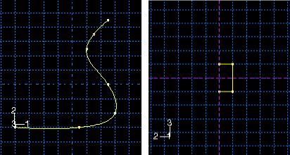
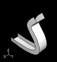
The sketch of the sweep path and the sketch of the sweep profile combine to define the swept shell feature, and both can be modified using the Feature Manipulation toolset. In addition, you can toggle on Keep internal boundaries in the Feature Manipulation toolset to maintain any faces or edges that are generated between the swept shell feature and the existing part. The internal boundaries may create regions that can be structured or swept meshed without having to resort to partitioning.
To add a swept shell feature:
From the main menu bar, select Shape![]() Shell
Shell![]() Sweep.
Sweep.
Abaqus/CAE displays prompts in the prompt area to guide you through the procedure.
Tip:
You can also add a swept shell feature using the ![]() tool, located with the shell tools in the Part module toolbox. For a diagram of the tools in the Part module toolbox, see “Using the Part module toolbox,” Section 11.17.
tool, located with the shell tools in the Part module toolbox. For a diagram of the tools in the Part module toolbox, see “Using the Part module toolbox,” Section 11.17.
If desired, specify the method you want to use to select an origin for your sketch of the swept shell feature. Select one of the following options from the Sketch Origin field in the prompt area:
Select Auto-Calculate to place the sketch origin automatically.
Select Specify to define a custom sketch origin.
Select Session Default to use the custom origin you specified earlier in the session.
Select the planar face on which to sketch the sweep path. If no suitable face exists, you can select a datum plane.
Tip: If you are unable to select the desired planar face, you can use the Selection toolbar to change the selection behavior. For more information, see “Using the selection options,” Section 6.3.
If you selected Specify as the Sketch Origin method, specify the origin location by clicking a point in the viewport or by entering the three-dimensional coordinates of the origin in the prompt area. You can also set this custom origin as the default origin for all sketches in your session by toggling on Set as session default.
Select an edge and the orientation of the edge on the Sketcher grid. The edge must not be perpendicular to the selected face. By default, the selected edge will appear vertical and on the right side of the Sketcher grid. To choose a different orientation for the edge, click the arrow on the right side of the dialog box and choose an orientation from the list that appears.
Tip: If the edge of the selected face is curved or does not provide the desired orientation, you can create a datum axis. You can then select the datum axis to control the orientation of the part on the Sketcher grid.
Abaqus/CAE highlights the selected edge, enters the Sketcher, and rotates the part until the selected face aligns with the plane of the Sketcher grid and the selected edge aligns with the grid in the desired orientation.
If you are unsure of the part's orientation relative to the Sketcher grid, use the view manipulation tools from the View Manipulation toolbar to view its position. Use the reset view tool ![]() to return to the original view.
to return to the original view.
Sketch the sweep path. The sweep path must meet the following guidelines:
The path can be closed, but the ends must meet smoothly; for example, the ends should not meet at a corner. For examples of valid sweep paths, see “Defining the sweep path and the sweep profile,” Section 11.13.8.
The path must be continuous; for example, it must not branch.
The resulting shell cannot intersect with itself.
Abaqus/CAE exits the Sketcher and restores the original view of the part. A highlighted line indicates the sweep path and its direction. You are now ready to sketch the sweep profile.
Select an edge and the orientation of the edge on the Sketcher grid. The selected edge must not be parallel to the sweep path direction. By default, the selected edge will appear vertical and on the right side of the Sketcher grid. To choose a different orientation for the edge, click the arrow on the right side of the dialog box and choose an orientation from the list that appears.
Abaqus/CAE highlights the selected edge, enters the Sketcher again, and rotates the part so that the Sketcher grid lies on a plane normal to the beginning of the sweep path with the sweep path direction pointing out of the screen. In addition, the selected edge aligns with the grid in the desired orientation. The intersection of two dashed lines indicates the origin of the sweep path.
Sketch the sweep profile. The sweep profile must meet the following guidelines:
The profile must be closed.
The resulting shell cannot intersect with itself.
Abaqus/CAE exits the Sketcher, restores the original view of the part, and creates the new swept shell. The resulting shell cannot intersect with itself.
