The control parameters for each bottom-up method are similar to the parameters used internally by Abaqus/CAE to create a comparable top-down swept mesh for a three-dimensional solid. The bottom-up methods and associated parameters are defined as follows:
Sweep
The sweep method creates a three-dimensional mesh by moving a two-dimensional mesh along a sweep path. The sweep method is illustrated in Figure 17–92. You should use the bottom-up sweep meshing method when the region cross-section changes between the starting and ending sides. To use the sweep method, you must first choose a Source side that defines the face or faces on which Abaqus/CAE will create a two-dimensional mesh. The source side can be any combination of geometric faces, element faces, and two-dimensional elements. You can define the sweep path by selecting Connecting sides that define the sides of the desired sweep region. If you define connecting sides, the mesh conforms closely to the geometry along the selected sides. Alternatively, you can select a Target side and specify a Number of layers and allow Abaqus/CAE to create the sweep path by interpolating between the source and target sides. The Target side is a single face that Abaqus/CAE uses to end the mesh. The number of layers refers to the number of element layers that will be placed between the source and the target sides—if you use connecting sides, the two-dimensional meshes of the connecting sides define the number of element layers. Abaqus/CAE sweeps the two-dimensional mesh from the source side into the volume of the solid region to create the mesh.
Extrude
The extrude method is a special case of the sweep method with a linear path defined by a direction and a distance. The extrude method is illustrated in Figure 17–93. You should use the extrude method for regions with a constant cross-section and a linear sweep path. There are three required parameters for a bottom-up extruded mesh. As with the sweep method, you choose the Source side that defines the area on which Abaqus/CAE will create a two-dimensional mesh. You then select the starting and ending point of a Vector that defines the extrusion direction and distance. Finally, you indicate the Number of layers to define the number of elements between the source side and the end of the extruded mesh. Abaqus/CAE extrudes the two-dimensional mesh from the source side along the extrusion vector and evenly divides the resulting region into the specified number of element layers.
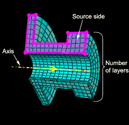
Revolve
The revolve method is another special case of the sweep method. In this case the sweep path is a circular path defined by an axis and an angle of revolution. The revolve method is illustrated in Figure 17–94. You should use this method for regions with a constant cross-section and a circular sweep path. As with the sweep and extrude methods, you choose the Source side that defines the area on which Abaqus/CAE will create a two-dimensional mesh. The source side cannot intersect the axis of revolution, but it may contain edges that coincide with the axis. If so, the elements contacting the axis create a layer of wedge elements in the revolved mesh. The source side should not include any triangular elements along the axis of revolution. You then select the starting and ending point of an Axis that defines the axis of revolution. Finally, you indicate the Angle and the Number of layers to define the number of elements between the source side and the end of the revolved mesh. Abaqus/CAE revolves the two-dimensional mesh from the source side by the specified angle and evenly divides the resulting region into the desired number of element layers. The direction of revolution is clockwise if you look along the axis of revolution from the starting point to the ending point.