
To obtain information on the mesh, select Tools![]() Query from the main menu bar. You can request information on the following:
Query from the main menu bar. You can request information on the following:
The total number of nodes and elements in a selected part, part instance, or region along with the number of elements of each element shape.
The type and connectivity of a selected element.
The positive and negative sides of shell and membrane faces.
The direction of beam and truss tangents.
The mesh stack orientation.
Whether any edges of boundary faces have incompatible interfaces, cracks, or gaps and whether any edges intersect other faces.
Whether there are free or non-manifold exterior element edges.
If the part or the assembly contains multiple meshed regions, use the following techniques to specify the region you want to query:
If the region contains a native mesh:
Use the mouse to select the desired region in the viewport, and then click mouse button 2 when your selection is complete. For more information on selecting objects, see Chapter 6, “Selecting objects within the viewport.”
If the region contains an orphan mesh imported from an output database:
Click Sets on the right side of the prompt area. A dialog box appears with a list of all of the element sets that you have created from the orphan mesh. Select the element set of your choice, and then click Continue. For information on creating sets, see Chapter 70, “The Set and Surface toolsets.”
To obtain mesh information:
From the Object field in the context bar, select a part or select the assembly.
From the main menu bar, select Tools![]() Query.
Query.
Tip:
You can also select the ![]() tool in the Query toolbar.
tool in the Query toolbar.
Abaqus/CAE displays the Query dialog box.
From the Query dialog box, select one of the following queries:
Shell/Membrane normals
Abaqus/CAE displays the part or the assembly using the shaded render style. The side of the shell where the surface normal coincides with the shell normal (top face) is shaded brown; the opposite side (bottom face) is shaded purple.
Beam/Truss tangents
Abaqus/CAE displays cyan arrows indicating the direction of the beam tangents.
Mesh stack orientation
For hexahedral and wedge elements, Abaqus/CAE colors the top face brown and the bottom face purple. Similarly, arrows indicate the orientation of quadrilateral elements. In addition, Abaqus/CAE highlights any element faces and edges that have inconsistent orientation.
Mesh
For an assembly, part or part instance, geometric region, or element, Abaqus/CAE displays the following:
The total number of nodes and elements in the selected area
The number of elements for each element shape
Element
Select an element. Abaqus/CAE displays the following in the message area:
The element label
The element topology
The element type that Abaqus/CAE will use for the analysis
Nodal connectivity
Mesh gaps/intersections
Select a part instance. Abaqus/CAE highlights any edges of boundary faces of the model in the current viewport with the following:
Incompatible interfaces
Cracks or gaps
Intersections with other faces
Free/Non-manifold edges
If the current viewport contains an assembly with more than one part instance, select one or more solid or shell instances for the query. Abaqus/CAE highlights two types of exterior element edges:
Free element edges are exterior edges that belong to a single exterior element face.
Non-manifold element edges are exterior edges shared by more than two adjacent exterior element faces.
Figure 17–133 Free element edges make up the exterior edges, and non-manifold edges form the center where the three planar shells are joined.
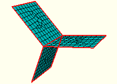
Shell parts should contain free edges and non-manifold edges where appropriate for the part design. Solid parts should not contain any free or non-manifold edges.
When you are finished obtaining mesh information, close the Query dialog box.
