You can study the onset and propagation of cracking in quasi-static problems using the extended finite element method (XFEM). XFEM allows you to study crack growth along an arbitrary, solution-dependent path without needing to remesh your model. XFEM is available only for three-dimensional solid and two-dimensional planar models; three-dimensional shell models are not supported. You can use XFEM to study a crack in an Abaqus native part or an orphan mesh part. You can choose to study a growing crack or a stationary crack. You define an XFEM crack in the Interaction module. During the analysis Abaqus/Standard determines the location of the crack based on the value of the maximum principal stress or strain calculated in the crack domain. For more information, see “Modeling discontinuities as an enriched feature using the extended finite element method,” Section 10.6.1 of the Abaqus Analysis User's Manual. Examples of XFEM models created in Abaqus/CAE are provided in “Modeling discontinuities using XFEM,” Section 1.19 of the Abaqus Benchmarks Manual.
To perform an XFEM crack analysis, you must specify the following:
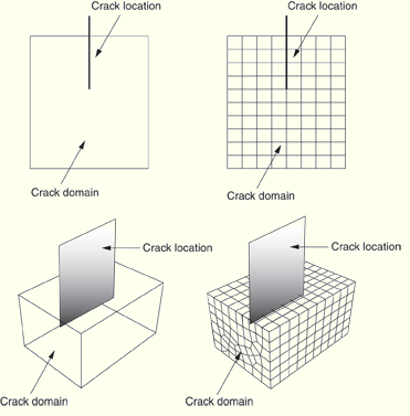
Crack domain
To define the crack domain, you can select one or more cells of a three-dimensional Abaqus native part or one or more faces of a two-dimensional planar native part. If you are defining the crack domain on an orphan mesh part, you can select elements. The crack domain includes regions that contain any existing cracks and regions in which a crack might be initiated and into which a crack might propagate.
Initial crack location
To define the initial crack location, you can select faces from a three-dimensional solid or edges from a two-dimensional planar model. The initial crack location must be contained within the crack domain. A selected face can be a face of the solid, a face created by a partition, or a planar part instance. Similarly, a selected edge can be an edge of the solid, an edge created by a partition, or a wire part instance; you should not select a seam crack. You should not mesh the faces or edges that you selected to define the initial crack location. Figure 29–14 shows examples of the crack domain and the crack location for two- and three-dimensional native and orphan mesh parts.
Alternatively, you can choose not to define the initial crack location. Regardless of whether you define the initial crack location, Abaqus initiates the creation of cracks during the simulation by searching for regions that are experiencing principal stresses and/or strains greater than the maximum damage values specified by the traction-separation laws.
Contact interaction property
You can choose to associate a contact interaction property with the XFEM crack that defines the contact of cracked element surfaces. For detailed information, see “Specifying a contact interaction property for XFEM,” Section 29.3.5.
Damage initiation and evolution criteria
You must specify the conditions that will initiate a crack by specifying damage initiation criteria in the material definition. You can specify a criterion based on either maximum principal stress or maximum principal strain. You can also specify the material properties that define the evolution of damage leading to eventual failure. You apply the material to the section that is assigned to the crack domain. For more information, see “Maximum principal stress or strain damage” in “Defining damage,” Section 12.9.3.
For detailed instructions, see “Creating an XFEM crack,” Section 29.3.3.