
If the region is a shell, you must assign the swept meshing technique; if the region is a solid, you can assign either the swept meshing technique or the bottom-up meshing technique. The swept meshing technique ensures that the elements are stacked in a manner suitable for gasket modeling. When you mesh shell or solid regions, the axis of each gasket element is coincident with the sweep path direction; therefore, you can control gasket element alignment by specifying an appropriate sweep path. When you use the bottom-up meshing technique you must make sure that the elements are stacked to provide the desired gasket orientation.
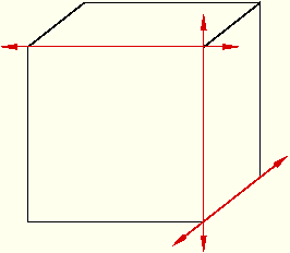
For example, the part instance shown in Figure 30–3 has three possible sweep paths, and each path has two possible sweep directions. If you mesh this part instance using gasket elements, you can choose from six possible gasket axis orientations. For more information, see “Swept meshing,” Section 17.9, and “Specifying the sweep path,” Section 17.17.6.
Figure 30–3 You must choose a sweep path and direction that provides an appropriate gasket axis orientation for your model.
In addition, you can assign gasket elements to an orphan mesh part. You can use the Query toolset to verify that the gasket elements are aligned correctly for regions where the gasket axis has more than one possible orientation. If necessary, you can use the Edit Mesh toolset to change the mesh stack orientation. For more information, see “Orienting the stack direction,” Section 61.6.4. You can use these tools with hexahedral, wedge, and quadrilateral elements because these are the only elements that can be stacked to form a continuum shell or gasket mesh. If you have assigned second-order gasket elements to the region, you must first change the assignment to conventional elements before you reorient the stack direction. You can then convert the region back to a gasket mesh by reassigning second-order gasket elements.