If you use wire parts to model beams, you must create a beam section that refers to a beam profile, and you must assign the beam section to the wire part. In addition, you must assign a beam orientation to the wire part. You can then use the View![]() Part Display Options and the View
Part Display Options and the View![]() Assembly Display Options menu items to view an idealized representation of the beam profile in parts and the assembly in the current viewport. During postprocessing, you can display the same representation of the beam profile for results data by selecting View
Assembly Display Options menu items to view an idealized representation of the beam profile in parts and the assembly in the current viewport. During postprocessing, you can display the same representation of the beam profile for results data by selecting View![]() ODB Display Options in the Visualization module. Beam rendering is available in the Visualization module for undeformed and deformed plots only. For deformed plots Abaqus/CAE scales the displacement components of the deformation but does not scale the rotational components of the deformation when you change the deformation scale factor.
ODB Display Options in the Visualization module. Beam rendering is available in the Visualization module for undeformed and deformed plots only. For deformed plots Abaqus/CAE scales the displacement components of the deformation but does not scale the rotational components of the deformation when you change the deformation scale factor.
When beam profiles are displayed, Abaqus/CAE disables both view cuts and scaling and shrinking of the model. In addition, because the rendering of beam profiles requires the presence of beam orientation data in the output database, you can display beam profiles during postprocessing only if nodal output is requested in the model. For more information, see “Using a beam section integrated during the analysis to define the section behavior,” Section 25.3.6 of the Abaqus Analysis User's Manual.
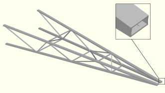
Displaying beam profiles is useful for checking that the correct profile has been assigned to a particular region and that the assigned beam orientation results in the expected orientation of the profile. For example, Figure 72–6 shows the box beam profiles displayed on the light-service crane described in “Example: cargo crane,” Section 6.4 of Getting Started with Abaqus: Interactive Edition.
If you assign a general beam section to a wire, Abaqus/CAE displays the beam profile as an ellipse with a cross-sectional area and moments of inertia (![]() and
and ![]() ) that match the values you specified. If you assign a truss section to a wire, Abaqus/CAE displays the truss profile as a circle with a cross-sectional area that matches the value you specified.
) that match the values you specified. If you assign a truss section to a wire, Abaqus/CAE displays the truss profile as a circle with a cross-sectional area that matches the value you specified.
Abaqus/CAE renders beam profiles according to the current settings for color coding and translucency. When these settings change, the color and translucency of the beam profiles change as well.
To control beam profile display:
Locate the Render beam profiles option.
From the main menu bar, select View![]() Part Display Options, View
Part Display Options, View![]() Assembly Display Options, or View
Assembly Display Options, or View![]() ODB Display Options. In the dialog box that appears, click the General tab. The General form becomes available; the Render beam profiles option is across the bottom of the form.
ODB Display Options. In the dialog box that appears, click the General tab. The General form becomes available; the Render beam profiles option is across the bottom of the form.
Toggle on Render beam profiles to display beam profiles.
If desired, apply a Scale factor to the beam profiles to increase or decrease their size. The default value is 1.
Click OK to implement your changes and to close the dialog box.
Abaqus/CAE displays the profile of the beam section with the appropriate dimensions and in the correct orientation. Your changes are saved for the duration of the session.